 BoreTherm
Borehole cross-section
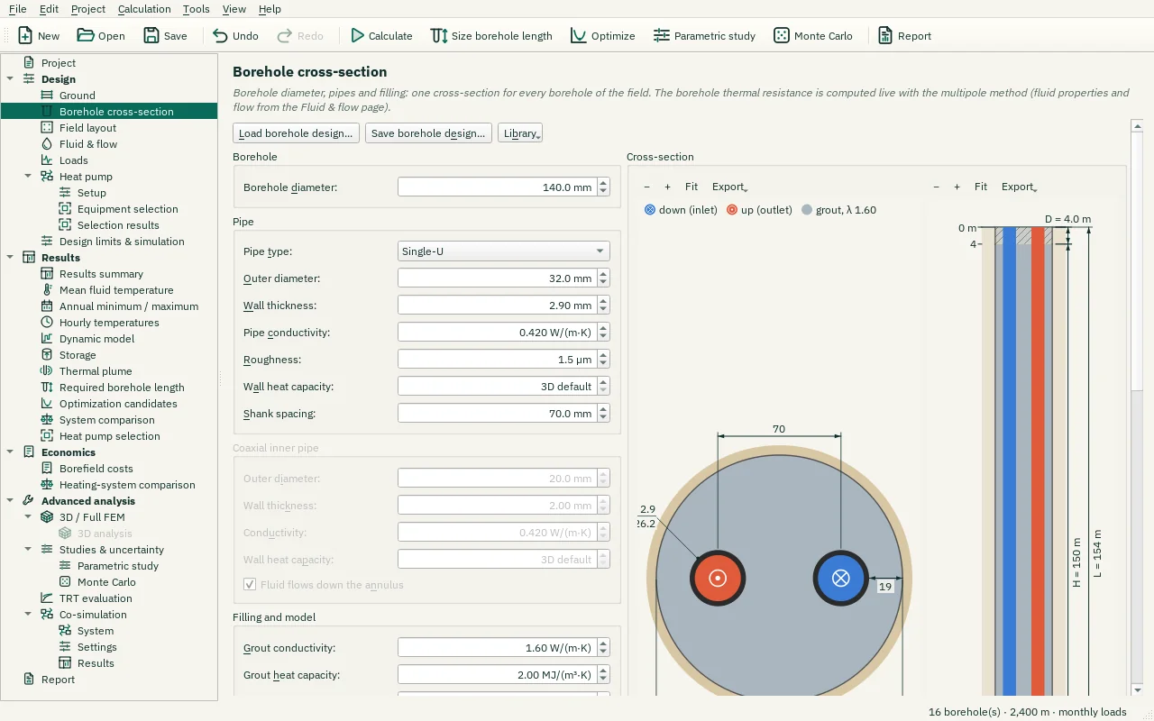
One cross-section for every borehole of the field. Enter the borehole diameter (it sets every borehole in one undo step; a hint shows when a custom layout has individual diameters in the Field layout table). Select single-U, double-U or coaxial construction. Enter pipe dimensions, shank spacing and material conductivity. Check the pipe geometry fits the borehole; the software rejects impossible dimensions. Sections describe construction changes along depth. Borehole resistance and hydraulic results are calculated from the selected construction and flow.
Step-by-step workflows · Menus and keyboard
| Control | Meaning / action | Unit | Range / choices | Example value |
|---|---|---|---|---|
| Load borehole design… | Load a saved borehole design (.btbh) or the design of another project: pipes, grout, sections, insulation, the resistance model and the borehole diameter. The field, the ground and the loads stay as they are. | |||
| Save borehole design… | Save this borehole design as a file (.btbh) to use it again in other projects. | |||
| Library | Typical designs and the designs saved in your library folder (Documents\BoreTherm\Borehole designs). | |||
| Undo | Restore the borehole design from before the load. | |||
| × | Hide this note (keep the loaded design). | |||
| Borehole diameter: | Borehole diameter 2·rb (drill diameter; for an energy pile the pile diameter). Typically 110 – 180 mm. A change sets every borehole of the field; boreholes of a custom layout can have their own diameter in the table of the Field layout page. | mm | 20 to 2000 | 140 |
| Pipe type: | Pipe configuration: single-, double- or triple-U tubes, a coaxial pipe, 4 to 8 U-tubes (multi-U, e.g. the loops of an energy pile) or a helix (spiral coil of an energy pile). | Single-U / Double-U / Triple-U / Coaxial / Multi-U (4–8) / Helix (spiral coil) | ||
| Outer diameter: | Outer diameter of the U-pipe legs (or of the outer pipe for coaxial). Common PE sizes: 25, 32, 40 mm. | mm | 5 to 300 | 32 |
| Wall thickness: | Pipe wall thickness. PE100 SDR11: 32 × 2.9 mm, 40 × 3.7 mm. | mm | 0.1 to 50 | 2.9 |
| Pipe conductivity: | Thermal conductivity of the pipe wall. PE100 ≈ 0.42, PE-X ≈ 0.38, steel ≈ 45. | W/(m·K) | 0.01 to 400 | 0.42 |
| Roughness: | Absolute inner roughness (friction factor, pressure drop). PE ≈ 1.5 µm. | µm | 0 to 5000 | 1.5 |
| Wall heat capacity: | Volumetric heat capacity of the pipe wall (U-pipe legs, or the outer pipe for coaxial): PE / PE-X ≈ 1.8, steel ≈ 3.6. Used only by the full transient boreholes of the 3D analysis (Full FEM). 3D default: the value of the Transient boreholes page. Sections can have their own value. | MJ/(m³·K) | 0 to 10 | 0 |
| Shank spacing: | Shank spacing: centre-to-centre distance between opposite U-pipe legs. Larger spacing lowers Rb. | mm | 5 to 2000 | 70 |
| U-tubes: | Number of U-tubes on the shank circle (multi-U), e.g. the loops of an energy pile on its reinforcement cage. The legs are spaced evenly. | 4 to 8 | 4 | |
| Helix pitch: | Helix: axial distance between two turns of the spiral coil. The coil diameter is the shank spacing; the return pipe runs on the pile axis. | mm | 10 to 2000 | 250 |
| U-loops: | How the U-loops of the energy pile are connected.In parallel: the flow splits over the loops between two manifolds at the pile head.In series: one continuous circuit; the fluid passes the legs one after another around the cage (numbered in the cross-section), and every pipe carries the whole flow of the pile. This gives turbulent flow at lower pile flows (lower Rb*), but a pressure drop over the full pipe length.Energy piles with two or more loops only (Energy pile below); not with borehole sections. | In parallel (manifold at the pile head) / In series (one circuit around the cage) | ||
| Outer diameter: | Outer diameter of the inner pipe (coaxial). | mm | 5 to 300 | 20 |
| Wall thickness: | Wall thickness of the inner pipe. | mm | 0.1 to 50 | 2 |
| Conductivity: | Conductivity of the inner pipe wall. An insulating inner pipe reduces the thermal short-circuit between the flow channels. | W/(m·K) | 0.01 to 400 | 0.42 |
| Wall heat capacity: | Volumetric heat capacity of the inner pipe wall (full transient boreholes of the 3D analysis). 3D default: the value of the Transient boreholes page. | MJ/(m³·K) | 0 to 10 | 0 |
| Fluid flows down the annulus | Checked: inlet in the annulus, return through the inner pipe (usual for heating). | |||
| Grout conductivity: | Thermal conductivity of the borehole filling (grout). Bentonite ≈ 0.7 – 0.8, thermally enhanced grout 1.6 – 2.3, groundwater-filled ≈ 0.6. | W/(m·K) | 0.1 to 10 | 1.6 |
| Grout heat capacity: | Volumetric heat capacity of the grout, used by the short-time and the dynamic borehole models (Design limits simulation page). Bentonite and cement grouts ≈ 1.6 – 2.5 MJ/(m³·K), water 4.2. | MJ/(m³·K) | 0.1 to 6 | 2 |
| Contact resistance: | Thermal resistance of the gap between each pipe and the grout (grout shrinkage, poor bonding, air pockets). It is added in series to the pipe resistance: Rp = convection + pipe wall + Rcontact.0 for well-bonded grout; up to about 0.03 m·K/W for poor contact. A higher value raises Rb*. | m·K/W | 0 to 0.2 | 0 |
| Multipole order: | Number of terms of the multipole method (Claesson amp; Hellström) that computes Rb and Ra from the pipe positions.J = 0 treats the pipes as line sources: fast, but less accurate when pipes are close to each other or to the borehole wall. Each higher order corrects the temperature distortion around the pipes; J = 3 is accurate within about 1 %, more is rarely needed (up to 10). | 0 to 10 | 3 | |
| Energy pile (cast-in-place concrete pile) | The borehole is a foundation pile: the grout values are the concrete's and the shank spacing is the diameter of the pipe circle on the reinforcement cage.The short-time borehole model then uses the ring model of the pile (concrete core, pipe ring, cover), the results include a thermo-mechanical screening and the TRT evaluation fits the pile model. | |||
| Undo | Restore the previous boundary condition. | |||
| × | Hide this note (keep UHTR). | |||
| Concrete expansion: | Thermal expansion coefficient of the pile concrete, for the thermo-mechanical screening (Results summary). Concrete ≈ 8 – 12 µm/(m·K). | µm/(m·K) | 0.1 to 30 | 10 |
| Concrete modulus: | Young's modulus of the pile concrete, for the fully restrained stress E α ΔT of the screening. C30/37 ≈ 33 GPa. | GPa | 1 to 100 | 30 |
| Lowest pile inlet temperature: | Lowest field inlet temperature for the pile, the coldest fluid at the concrete. The results warn below it; the length is still sized on the mean fluid temperature limits.0 °C (SIA D0190, VDI 4640) is the default; some designs use 2 °C (Phillips et al. 2010, Loveridge amp; Powrie 2013), so that neither the concrete nor the ground at the pile freezes. | °C | -20 to 30 | 0 |
| Highest pile inlet temperature: | Highest field inlet temperature for the pile, the warmest fluid at the concrete in cooling. The results warn above it.40 °C is the default (average pile temperature changes up to about +30 K, Laloui amp; Rotta Loria 2020); Loveridge amp; Powrie (2013) use 32 °C. | °C | 0 to 90 | 40 |
| Convection: | Convective heat transfer correlation inside the pipes.Gnielinski (default): Nu = 3.66 for Re ≤ 2300, Gnielinski for Re ≥ 4000, linear blend in between.Colburn: Nu = 4.0 for Re lt; 2300, Nu = 0.023 Re0.8 Pr1/3 above, without a transition blend. Set by the classic-method compatibility preset (Simulation page).Coaxial pipes: applies to the inner pipe only. | Gnielinski, blended transition / Colburn, no transition | ||
| Fixed Rb*: | Use a constant effective borehole resistance Rb* instead of the computed one (e.g. from a thermal response test). It is used at every borehole length during sizing. Rb, Ra, Re and the pressure drop are still computed. | |||
| The imposed effective borehole resistance Rb* (typical 0.06 – 0.20 m·K/W). | The imposed effective borehole resistance Rb* (typical 0.06 – 0.20 m·K/W). | m·K/W | 0.001 to 2 | 0.1 |
| − | Zoom out (−, mouse wheel) | |||
| + | Zoom in (+, mouse wheel) | |||
| Fit | Show the whole drawing (0, double-click). Drag to pan. | |||
| Export | Save the drawing as shown as a PNG image or an SVG vector graphic. | |||
| Add section | Add a section of 10 m below the deepest one (the first one starts at the top of the active length). | |||
| Duplicate | Copy the selected sections below the deepest one. | |||
| Remove | Remove the selected evaluation item or interval from this table. | |||
| Presets | Add a typical section. All values can be edited afterwards. | |||
| Materials | Set the grout or the insulation conductivity of the selected sections from typical values (VDI 4640 Blatt 6 for grouts; manufacturer data for insulation). | |||
| × | Hide this note (keep UFT). | |||
| Lowest pile inlet temperature: | Lowest field inlet temperature for the pile, the coldest fluid at the concrete. The results warn below it; the length is still sized on the mean fluid temperature limits.0 °C (SIA D0190, VDI 4640) is the default; some designs use 2 °C (Phillips et al. 2010, Loveridge amp; Powrie 2013), so that neither the concrete nor the ground at the pile freezes. | °F | -4 to 86 | 32 |
| Highest pile inlet temperature: | Highest field inlet temperature for the pile, the warmest fluid at the concrete in cooling. The results warn above it.40 °C is the default (average pile temperature changes up to about +30 K, Laloui amp; Rotta Loria 2020); Loveridge amp; Powrie (2013) use 32 °C. | °F | 32 to 194 | 104 |