 BoreTherm
Field layout
Choose a head pattern, dimensions, spacing and rotation, then an independent inclination mode. H is drilled axis length; tilt is measured from vertical. The borehole diameter is set on the Borehole cross-section page. Custom fields allow individual coordinates, lengths, depths and diameters; Apply to selected / all copies H and D only. Intersecting axes are errors; close axes produce a warning with the named pair. Plan, 3D and Site views describe the same field. Site mode supports boundaries, exclusions, backgrounds, calibration, automatic fill and connection networks. Export FMU is a preview workflow.
Step-by-step workflows · Menus and keyboard
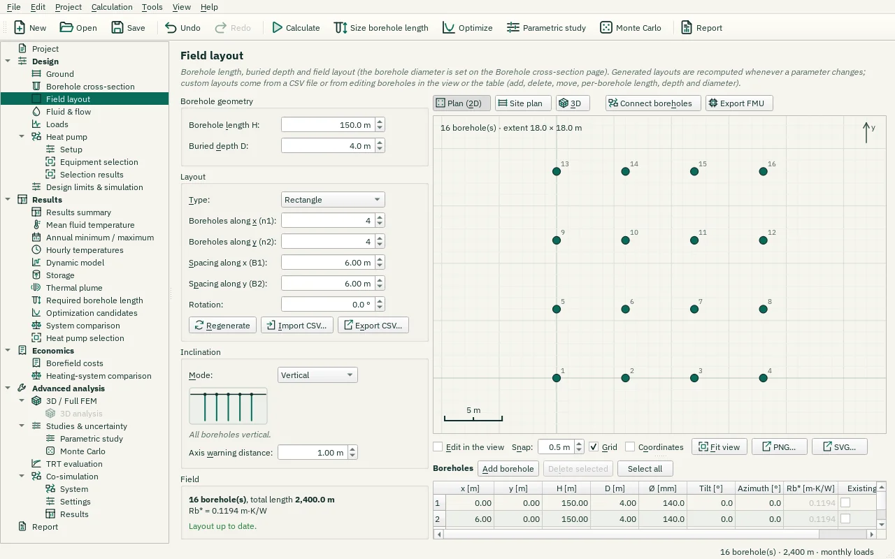
| Control | Meaning / action | Unit | Range / choices | Example value |
|---|---|---|---|---|
| Borehole length H: | Active borehole length H (depth of the heat-exchanging part). Generated layouts: applies to all boreholes. Custom layouts: used for new boreholes. | m | 1 to 3000 | 150 |
| Buried depth D: | Buried depth D of the borehole top below the ground surface (non-exchanging header section). Typically 0 – 5 m. | m | 0 to 500 | 4 |
| Apply to selected | Set H and D of the selected boreholes to the values above (their diameters stay). | |||
| Apply to all | Set H and D of every borehole to the values above (their diameters stay). | |||
| Type: | Borehole configuration. Custom: positions from a CSV file or edited in the view and the borehole table. Choosing a generated type replaces the field. | Single borehole / Line / L-shape / L2-shape (double L) / U-shape / Open rectangle / Rectangle / Circle / Hexagonal / Concentric rings / Custom (CSV / edited) | ||
| Boreholes along x (n1): | Number of boreholes along x (first direction). | 1 to 200 | 4 | |
| Boreholes along y (n2): | Number of boreholes along y (second direction). | 1 to 200 | 4 | |
| Spacing along x (B1): | Borehole spacing along x (centre to centre). Typically 5 – 10 m, with B/H between 0.02 and 0.5. | m | 0.5 to 500 | 6 |
| Spacing along y (B2): | Borehole spacing along y (centre to centre). | m | 0.5 to 500 | 6 |
| Boreholes per ring: | Number of boreholes on each ring from the inside out, separated by semicolons, e.g. "1; 6; 12; 18" (a first ring of one borehole is the centre borehole). Empty: a centre borehole and the number of rings above with 6, 12, 18, … boreholes. | |||
| Ring radii [m]: | Radius of each ring [m] from the inside out, separated by semicolons, e.g. "0; 5; 10; 15" (0 for a centre borehole). Empty: equal steps of the ring spacing. | |||
| Rotation: | Rotation of the pattern about its first borehole (the origin), counter-clockwise from +x (east) towards +y (north). The inclination turns with it, except the azimuth of Same direction, which is a compass direction. | ° | -360 to 360 | 0 |
| Regenerate | Recompute the borehole positions from the layout parameters. | |||
| Import CSV… | Load a custom layout: CSV with columns x, y [, H [, D [, rb [, tilt_deg [, azimuth_deg]]]]] in metres and degrees (header line optional). Missing columns use the values above and the diameter of the Borehole cross-section page. | |||
| Export CSV… | Write the displayed numerical table to a CSV file using the selected CSV format. | |||
| Mode: | How the boreholes are inclined. Vertical: all straight down. Same direction: all tilted the same way. Radial outwards: tilted away from a centre. Radial fan: the tilt grows towards the edge. Arc: the tilt changes evenly along an axis. | Vertical / Same direction / Radial outwards / Radial fan / Arc | ||
| Tilt: | Tilt of every borehole from the vertical (at most 85°). A negative tilt points the other way. | ° | -85 to 85 | 20 |
| Tilt spread: | Arc: total tilt range along the arc axis, from the centre tilt minus half the spread to the centre tilt plus half the spread. A negative angle points the other way. Every tilt must stay within 85° of the vertical. | ° | 0 to 170 | 20 |
| Azimuth: | Direction in the plan towards which every borehole is tilted, from +x (east) towards +y (north). It does not turn with the pattern's rotation. | ° | -360 to 360 | 0 |
| Arc axis: | Arc: the direction along which the tilt changes, from the rows of the pattern (0° = along the rows), turned with the pattern. Positive tilts point in this direction. Shown in the plan while this field has the focus. | ° | -360 to 360 | 0 |
| Centre: | Where the radial modes measure from: the centre of the borehole heads, the head of the first borehole, or a point x, y. Shown in the plan while these fields have the focus. | Field centre / First borehole / Point | ||
| Centre x: | x of the centre point (east). | m | -100000 to 100000 | 9 |
| Centre y: | y of the centre point (north). | m | -100000 to 100000 | 9 |
| Centre borehole vertical | Radial outwards: a borehole exactly at the centre has no outward direction; checked, it stays vertical, otherwise it is tilted towards the azimuth offset. | |||
| Apply inclination… | Set the tilt and azimuth of every borehole of the custom field from an inclination mode (once; Ctrl+Z undoes it). Single boreholes can be changed in the table. | |||
| Axis warning distance: | Two borehole axes closer than this distance give a warning (drilling tolerance). Axes closer than the sum of the two borehole radii are an error: the boreholes intersect. | m | 0 to 100 | 1 |
| Add borehole | Add a borehole with the geometry above next to the field (the layout becomes Custom). In edit mode you can also double-click in the view. | |||
| Delete selected | Delete the selected boreholes (the layout becomes Custom). At least one remains. | |||
| Select all | Select all available rows/items in this view. | |||
| Plan (2D) | Top view of the field with the borehole editor (select, move, add, delete). | |||
| 3D | 3D view of the boreholes along their axes, to check inclined boreholes, with the clearance check between the borehole axes. | |||
| Site plan | The plan view with the site plan: load a DXF drawing or a picture, draw drilling areas, no-go zones and corridors, fill the areas with boreholes and check the field against them. | |||
| Connect boreholes | Connection editor in the plan (the 3D view switches to Plan (2D) and stays off while connecting): click a borehole, then the next to connect them in the flow direction; drag across boreholes to chain them; click a link and press Del to remove it. Patterns, undo and the validation are under the view. Off: the layout editor. | |||
| Export FMU | Export FMU | |||
| Top | View from above, north up. | |||
| South | View from the south, looking north. | |||
| East | View from the east, looking west. | |||
| Isometric | Oblique view from the south-west (also: Home key). | |||
| Fit | Fit the field into the view, keeping the direction (also: double-click). | |||
| Perspective | Perspective projection: nearer parts look larger. Off: orthographic, the same scale everywhere. | |||
| Depth scale: | Vertical exaggeration of the depth (1 = true scale). Values below 1 compress deep fields, values above 1 stretch shallow ones. | × | 0.1 to 20 | 1 |
| PNG… | Export the 3D view as a PNG image. | |||
| SVG… | Export the 3D view as a vector SVG image (for Word, Inkscape, …). | |||
| Ground layers | Show the ground layers as translucent slabs with their names (layered ground only). | |||
| Sections | Show the borehole sections (insulated casing, pipe sleeve, other diameter or grout) as thick segments along each borehole. | |||
| Buried part | Show the buried part above each borehole head (dashed), continued along the axis up to the ground surface. | |||
| Site plan | Show the site plan on the ground surface, under the boreholes: the plan loaded in Site plan mode (with its opacity) and the drilling areas, no-go zones, corridors, connection point and trench (also in exported pictures). Available when the project has a site plan or site areas. | |||
| Piles to scale | Energy piles (Borehole cross-section page): draw each pile as a concrete cylinder at its true diameter, with the pipes inside (U-tubes on the reinforcement cage, or the helix) when you zoom in. | |||
| Grid | Show the grid lines (plan and 3D view; also in exported pictures and the report). | |||
| Coordinates | Show coordinates in metres: values along the edges, the cursor position and each borehole's x, y next to its number (plan and 3D view; also in exported pictures and the report). | |||
| Including the buried part | Also check the buried part between the ground surface and the borehole head, e.g. for inclined boreholes drilled from a common shaft or collar. | |||
| Clearance check below: | Clearance check: pairs of boreholes whose axes come closer than this distance (minimum 3D distance over the active length) are highlighted in the 3D view, listed below and reported as a warning. | m | 0 to 100 | 3 |
| Select | SelectSelect and edit: drag a corner to move it, double-click an edge to add a corner, right-click a polygon for its menu, Del deletes the selected polygon. | |||
| Measure | MeasureMeasure a distance: click two points (Shift: 45° steps). | |||
| Drilling area | Drilling areaDraw a drilling area: boreholes are allowed inside it. | |||
| No-go zone | No-go zoneDraw a no-go zone: a building, tree, pond or neighbour's setback where no borehole may be drilled. | |||
| Corridor | CorridorDraw a utility corridor: a buried pipe, cable or sewer with a clearance on both sides. | |||
| Reference | ReferenceDraw a reference outline (shown only, no rule). | |||
| Connection point | Connection pointClick the connection point: the manifold or the building entry the trench leads to. | |||
| CAD polyline | CAD polylineClick a polyline of the DXF drawing to use it exactly as a polygon (the kind is chosen with the arrow). | |||
| Set scale | Apply the drawing scale calculated from the selected calibration points and known distance. | |||
| Move / rotate plan | Move / rotate planMove, rotate or scale a picture of the plan: drag it to move it (Shift: along x or y), drag the round handle to rotate it about its centre (Shift: 15° steps), drag a corner to scale it about the opposite corner, Ctrl+wheel scales it about the cursor. Exact values: Placement in the Plan tab. | |||
| Undo | Undo the last change of the project, e.g. of the site plan or a fill (Ctrl+Z). | |||
| Snap to corners | New and moved corners snap to the corners of the polygons and of the drawing within 10 px, otherwise to the grid of the plan view (Snap). | |||
| Fill area… | Fill the drilling areas with boreholes (grid, staggered, row-wise or along the edge) with a preview. | |||
| Delete polygon | Delete the selected polygon (also: Del in the plan view). | |||
| Minimum borehole distance: | Smallest distance allowed between two borehole heads (0 = only no overlap). | m | 0 to 100 | 0 |
| Clear | Remove the currently loaded series from this input. | |||
| Load plan… | Load a site plan as the background: a DXF drawing (AutoCAD, BricsCAD, LibreCAD, QGIS export), a PNG/JPEG image or an SVG drawing. | |||
| Remove | Remove the selected evaluation item or interval from this table. | |||
| Show the plan | Enables or disables this option. | |||
| Lock the plan | Protects the plan against changes: loading, removing, units, scale and position. | |||
| Store the plan in the project | Keeps a copy of the plan file in the project file, so the project can be passed on or moved without the plan file. Unchecked, the project refers to the file by its path. Plans over 20 MB make the project file large. | |||
| Export the stored plan… | Writes the plan stored in the project to a file. | |||
| Drawing units: | Unit of the DXF coordinates. The drawing's own unit ($INSUNITS) is used unless another one is chosen; drawings without a unit are read in metres. | From the drawing / mm / cm / m / km / in / ft | ||
| PDF page: | Page of the PDF document shown. | 1 to 9999 | 1 | |
| Centre x: | Site coordinates of the picture's centre. Rotating or scaling the picture keeps its centre in place. | m | -1e+07 to 1e+07 | 0 |
| Centre y: | Site coordinates of the picture's centre. Rotating or scaling the picture keeps its centre in place. | m | -1e+07 to 1e+07 | 0 |
| Metres per pixel: | Metres per pixel of the picture; its centre stays where it is. | 1e-06 to 1000 | 1e-06 | |
| Rotation (counter-clockwise): | Rotation of the picture counter-clockwise; 0° = the top of the picture points north. It turns about the picture's centre, as the rotation handle and "Reset rotation" do. | ° | -180 to 180 | 0 |
| Reset rotation | Turn the picture back to north up (about its centre). | |||
| Fit plan to the field | Move and scale the picture so that it covers the borehole field (or the site polygons) with a margin; the rotation is kept. A rough start before Set scale. | |||
| Use layer as | Every closed polyline of the selected layer becomes a polygon of the chosen kind (open polylines: corridors or references only). | |||
| Edit in the view | When checked, the selected boreholes can be moved with the mouse, a drag on the background selects boreholes, a double-click adds a borehole and Del deletes the selected ones. Any edit makes the layout Custom. | |||
| Fit view | Adjust zoom and camera so the full drawing/field fits the view. | |||
| Snap: | Grid for moved and added boreholes (0 = off). | m | 0 to 10 | 0.5 |
| PNG… | Export the top view as a PNG image. | |||
| SVG… | Export the top view as a vector SVG image (for Word, Inkscape, …). | |||
| Connection pattern, applied with Apply (one undo step). Radial strings: strings of equal length from the centre to the edge. Sectors: one string per sector of equal angle. Ring-wise: each ring is a group of boreholes in parallel, the rings in series (several sectors give several such strings). | Connection pattern, applied with Apply (one undo step). Radial strings: strings of equal length from the centre to the edge. Sectors: one string per sector of equal angle. Ring-wise: each ring is a group of boreholes in parallel, the rings in series (several sectors give several such strings). | All in parallel / Rows in series / Columns in series / Serpentine / Nearest neighbour from the selected borehole / Tichelmann (reverse return) / Radial strings (centre – edge) / Sectors / Ring-wise (rings in parallel groups) | ||
| Boreholes per string (0 = whole rows, one string), or the number of strings or sectors of the radial, sector and ring-wise patterns. | Boreholes per string (0 = whole rows, one string), or the number of strings or sectors of the radial, sector and ring-wise patterns. | 0 to 1000 | 0 | |
| Flow direction of the radial, sector and ring-wise patterns. Centre → edge: the warmest fluid enters at the centre, which keeps a warm core (charging). Edge → centre: the reverse (discharging). | Flow direction of the radial, sector and ring-wise patterns. Centre → edge: the warmest fluid enters at the centre, which keeps a warm core (charging). Edge → centre: the reverse (discharging). | Centre → edge (charging) / Edge → centre (discharging) | ||
| Apply | Apply changes and keep the dialog open. | |||
| Undo | Undo the last change of the project, e.g. of the connections (Ctrl+Z). | |||
| Redo | Redo the change undone last (Ctrl+Y). | |||
| Reset | Back to the default: all boreholes in parallel, equal flow, no minor losses, series factor 1. | |||
| Header | Show the header (supply and return manifold) with its lines to the string inlets and outlets: at the site's connection point, else south of the field. | |||
| Azimuth offset: | Angle added to the outward direction of every borehole (0 = straight outwards; other values make a spiral). | ° | -360 to 360 | 0 |
| Tilt at the edge: | Tilt from the vertical of the borehole farthest from the centre; the tilt of the others grows with their distance from the centre (tan(tilt) in proportion). A negative tilt points inwards (refused when the boreholes would meet). | ° | -85 to 85 | 20 |
| Centre tilt: | Tilt from the vertical in the middle of the arc axis; the spread gives the tilts at its ends. The length H is measured along each straight borehole. | ° | -85 to 85 | 20 |
| Setback: minimum distance of a borehole from this polygon's edge [m]. | Setback: minimum distance of a borehole from this polygon's edge [m]. | 0 to 100 | 1 | |
| Rings around the centre: | Hexagonal rings around the centre borehole: 1, 2, 3, 4 rings give 7, 19, 37, 61 boreholes. | 1 to 30 | 3 | |
| Spacing B: | Distance between neighbouring boreholes of the hexagonal field (centre to centre). | m | 0.5 to 500 | 3 |
| Borehole length H: | Active borehole length H (depth of the heat-exchanging part). Generated layouts: applies to all boreholes. Custom layouts: used for new boreholes. | ft | 3.3 to 9842.5 | 492.1 |
| Buried depth D: | Buried depth D of the borehole top below the ground surface (non-exchanging header section). Typically 0 – 5 m. | ft | 0 to 1640.4 | 13.1 |
| Spacing along x (B1): | Borehole spacing along x (centre to centre). Typically 5 – 10 m, with B/H between 0.02 and 0.5. | ft | 1.64 to 1640.42 | 19.69 |
| Spacing along y (B2): | Borehole spacing along y (centre to centre). | ft | 1.64 to 1640.42 | 19.69 |
| Centre x: | x of the centre point (east). | ft | -328084 to 328084 | 29.53 |
| Centre y: | y of the centre point (north). | ft | -328084 to 328084 | 29.53 |
| Axis warning distance: | Two borehole axes closer than this distance give a warning (drilling tolerance). Axes closer than the sum of the two borehole radii are an error: the boreholes intersect. | ft | 0 to 328.08 | 3.28 |
| Clearance check below: | Clearance check: pairs of boreholes whose axes come closer than this distance (minimum 3D distance over the active length) are highlighted in the 3D view, listed below and reported as a warning. | ft | 0 to 328.1 | 9.8 |
| Minimum borehole distance: | Smallest distance allowed between two borehole heads (0 = only no overlap). | ft | 0 to 328.08 | 0 |
| Centre x: | Site coordinates of the picture's centre. Rotating or scaling the picture keeps its centre in place. | ft | -3.28084e+07 to 3.28084e+07 | 0 |
| Centre y: | Site coordinates of the picture's centre. Rotating or scaling the picture keeps its centre in place. | ft | -3.28084e+07 to 3.28084e+07 | 0 |
| Snap: | Grid for moved and added boreholes (0 = off). | ft | 0 to 32.8 | 1.6 |
| Spacing B: | Distance between neighbouring boreholes of the hexagonal field (centre to centre). | ft | 1.64 to 1640.42 | 9.84 |