A site plan describes where drilling is allowed: drilling areas (several form a union), no-go zones (buildings, trees, ponds, neighbours), corridors (buried pipes, cables, sewers) and information polygons, each with a setback. Coordinates are metres in the site frame (x east, y north), the frame of the borehole heads; CAD or UTM coordinates are shifted by the site origin. A background picture (image, PDF, SVG or DXF with a two-point calibration) is for display and the reports only. This is geometry, not physics: a field made inside a site is an ordinary custom field.
16.1 Region test
Point in polygon uses the winding number (non-zero rule), so concave outlines and either orientation work; a point within m of an edge counts as inside. With the signed distance to a polygon's outline (negative inside), the distance to a corridor and the setbacks, the clearance of a position is
over the drilling areas , the no-go zones and the corridors . A borehole may be drilled at when m. Without a drilling area only the no-go terms count; with several, the setback is measured to the area that contains the point best. The validation of a field lists, per head (the collar of an inclined borehole), every failing term with the distance found and the one required, and pairs closer than the minimum distance. Simulation and sizing do not block on violations.
16.2 Fill patterns
Every generator produces candidate positions and keeps those with ; a global minimum distance thins the result greedily. The row direction is given or, by default, that of the longest edge of the largest drilling area.
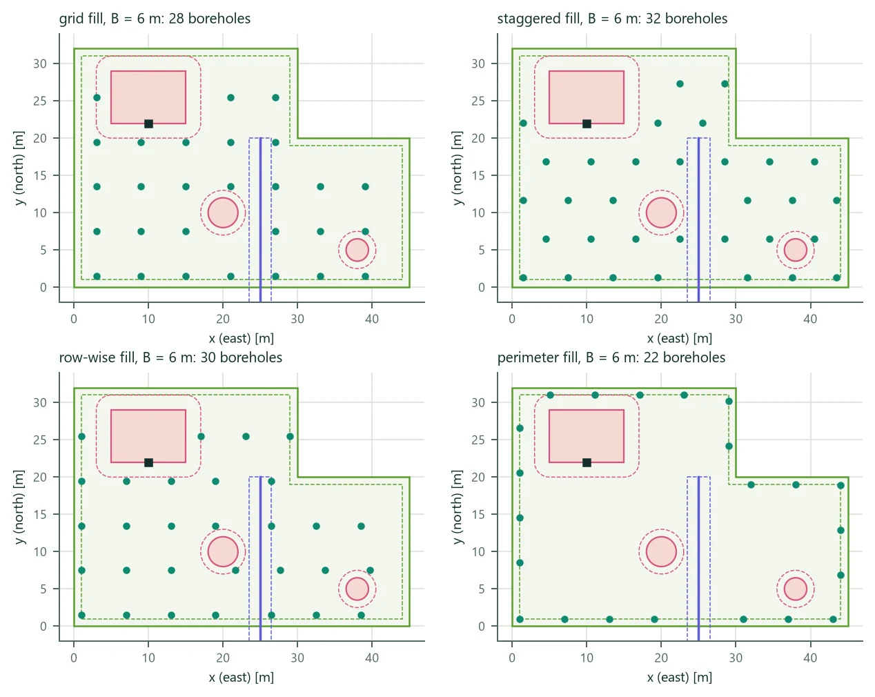
- Grid: with , ; the lattice offset is searched on a 4 × 4 grid within one cell for the most positions. A rectangular area gives the rectangle layout exactly, in the same order.
- Staggered: every other row shifted by with (hexagonal packing: every neighbour away, about 15 % more boreholes per area than a square grid).
- Row-wise (as in published row-wise placement methods): rows parallel to an edge, each packed from its first allowed position and continued after an obstacle, so rows start at the region's edge.
- Perimeter: along the outline offset inward by the setback, each position a chord from the previous one. Open layouts interact less than filled ones.
- Spread-first order: farthest-point sampling (first the head farthest from the centroid, then repeatedly the head farthest from those chosen), so the first heads are a well-spread subset of boreholes.
Figure 14 shows the four fills at 6 m on the L-shaped example site (a 1260 m² plot with a 1 m setback, a building with 2 m, two trees with 1 m and a sewer corridor with 1.5 m): 28 boreholes in the grid, 32 staggered, 30 row-wise and 22 on the perimeter. Every position respects every setback (the dashed lines).
16.3 Optimization inside the site
Optimization inside a site replaces the rectangular plot of (9.5) by the site plan; the two-stage search (screening with the equivalent-borehole g-function, exact re-sizing of the best) is that of Section 9.5. The candidates are the layout types placed in the site (for the directions of the four longest edges and a sweep every 15°, rotated by multiples of 90° and translated on a grid of steps plus the alignments with edges, setbacks and vertices, until every head is allowed) and the fills (one candidate per borehole count: the spread-first subset of the full fill). The trench is the minimum spanning tree of the heads plus the connection point. With a rectangular drilling area at the origin and no fills the site search reproduces the plot optimization exactly.
On the example site the stored search (spacing 5–12 m, 4–40 boreholes, five layout types, four fills, 15° sweep) screens 628 candidates in 3.3 s and re-sizes 29. The best candidate is the plot's best shape, an L of 8 boreholes (5 × 4, sharing the corner) at 10 m with H = 213.1 m, placed along the plot's edges at the setback; its trench of 77.1 m includes the connection at the building entry, and the cost is 92 744. The example's own field, a 16-borehole grid fill, needs 130.0 m per borehole.
16.4 DXF drawings
BoreTherm has its own reader of the public (ASCII) DXF format: HEADER units and extents, the LAYER table, BLOCKS and ENTITIES; LINE, LWPOLYLINE and POLYLINE with bulges, CIRCLE, ARC, ELLIPSE, SPLINE (NURBS by de Boor's algorithm), HATCH boundary loops, POINT, TEXT/MTEXT and INSERT (base point, scale, rotation, arrays, nested up to 16 levels); entities in an object coordinate system are mapped by the arbitrary-axis algorithm. A bulge is the tangent of a quarter of the included angle, so the arc has
with the distance of the centre from the chord's midpoint (to the left) and the chord length. Arcs are tessellated in steps of at most 5°; the site polygons are with the metres per drawing unit (\mathbf{o}$ the origin. Binary DXF is refused; paper space and unknown entities are skipped with a note.