An energy pile is a cast-in-place concrete foundation pile with heat exchanger pipes tied to its reinforcement cage. Thermally it is a short (10–40 m), wide (0.3–1.5 m) borehole whose filling is structural concrete. Two things set it apart from a borehole (Loveridge & Powrie 2013, 2014): the concrete stores much more heat than borehole grout, so the pile stays transient for days to months rather than hours; and the pipes lie near the perimeter, with a concrete core inside them and only the cover outside. Mechanically the pile carries the building: a temperature change makes it shorten or lengthen, or builds up stress where it cannot move.
A design is marked as an energy pile in the Energy pile group of the Borehole cross-section page. The borehole diameter is then the pile diameter, the grout values are those of the concrete, and the shank spacing is the diameter of the circle through the pipe centres (the cage diameter minus the bars and the cover). The steady model, the multipole pile resistance and the g-function keep their form; the short-time model uses the ring model of this chapter, the g-function boundary condition becomes a uniform heat flux, and the results add a thermo-mechanical screening and a check of the inlet temperatures at the pile.
20.1 Pipes on the cage
- U-loops in parallel. Single, double or triple U-tube, or 4 to 8 U-tubes on the cage of a large pile: legs every on the shank circle. The pile resistance and the internal resistance come from the multipole method with the concrete as grout, and from the short-circuit relations of a borehole.
- U-loops in series. One continuous pipe that runs down and up the cage times. Every pipe carries the whole flow of the pile, which keeps the flow turbulent at lower pile flows (lower pipe resistance) at the cost of a much higher pressure drop: about times for laminar, for turbulent flow in smooth pipes. is that of the whole circuit: the leg temperatures along the depth are solved with the conductance matrix of the multipole method and the boundary conditions at the toe and the head; for one loop this is the uniform-wall-temperature of a U-tube exactly.
- Spiral coil of pitch on the cage circle of diameter with a straight return pipe on the axis. Per metre of pile the coil length is , the turn spacing and the cover (); the pile resistance is the film and wall of the coil, the concrete cylinder from to and the local part of a row of tubes near an isothermal plane (conduction shape factor, Incropera et al. 2007):
with the concrete conductivity. Against an axisymmetric ring-coil model (the idealisation of Cui et al. 2011) this agrees within 0.6–0.8 %. Spiral coils are not available with borehole sections or the dynamic model.
20.2 The ring model of the concrete
The equivalent single pipe of the short-time model of boreholes puts all pipes on the axis and all filling outside them. For a pile that is the wrong geometry: a large part of the concrete is the core inside the pipe ring. The ring model resolves it. With the radius of the pipe centres, the outer pipe radius and the number of legs, the cross-section is
- the concrete core , a solid cylinder;
- the ring : the pipes and the concrete between them, with the capacity per metre;
- the concrete cover , then the ground.
The network is: fluid node (fluid and pipe walls of all legs) – resistance – pipe-zone node (the ring concrete) – resistance – ring junction. The junction connects inwards through to the core and outwards through to the pile wall. Without capacities no heat enters the core, so the steady fluid-to-wall resistance is
and is set to make it the multipole : the long-time end of the ring model is the steady model. must at least hold the film and wall resistances of the legs in parallel, ; when a small does not allow that, the cover conductivity is raised until , otherwise .
The concrete next to the pipes takes up heat before heat crosses the full concrete path to the ring. As for the grout node of the borehole network (Bauer et al. 2011), each leg owns its share of the ring, , a circle of radius , and the pipe-zone node sits at the radius that halves this area:
Typical piles give ; nothing is fitted. The finite volumes are those of the borehole radial model: 16 equal core cells, 8 cover cells and 90 logarithmically spaced ground cells, with second-order backward differences in time. The fluid and pipe-zone nodes are eliminated into the junction row, so a time step is one tridiagonal solve. The capacity correction is the difference of two runs with and without the capacities of fluid, pipes and concrete:
In the example pile below, the core holds about as much heat per kelvin as the cover (257 against 272 kJ/(m K)) and three times as much as the pipe ring.
20.2.1 Blend time per pile
The capacity effect of a pile decays slowly, roughly as : for a 1.2 m pile it is still 4 % of the response after 30 days and 1.7 % after 90 days. The fixed 100 h of boreholes would cut it off. The ring model is therefore run to one year to find the time from which the un-blended effect stays below 1 % of the response without capacities, and
so that the blend starts where the effect is already at most 1 %. Typical values: 39 days for a 0.3 m pile, 184 days for 0.6 m, one year for 0.9 m and above. Beyond one month the monthly base temperatures also get the correction, and long hourly convolutions run through the fast Fourier transform. Pipes near the axis (, a single U-tube on a centre bar) and coaxial pipes use the equivalent pipe, which is that geometry, and the results say so.
20.3 The ground side: g-function and the building above
The g-function of a pile group is the finite line source at the pile radius, with three points that matter for piles:
- Uniform heat flux. The pile literature uses the uniform-flux finite line source with the pile head at the surface (Loveridge & Powrie 2013; Laloui & Rotta Loria 2020). A uniform wall temperature is not conservative for short piles with the head near the surface, so ticking Energy pile sets the boundary condition to uniform heat flux (in the same undo step; the simulation warns about a uniform wall temperature near the surface).
- Cylindrical correction. At the pile's own radius the line source is too low for (2–20 days for 0.3–1 m piles). The cylindrical-source correction fixes this; the simulation warns when it is off.
- Finite against infinite cylinder. The ends of a short pile matter from a Fourier number on (Loveridge & Powrie 2013 find 2D and 3D results to differ by 10–15 % at Fo = 10). The finite line source holds these end effects, and by Fo ≈ 10 the cylinder correction is small, so adding the infinite-cylinder correction to the finite line source remains a good approximation. With the concrete core of the ring model the pile corresponds to the solid finite cylinder source of Man et al. (2010).
The building above the piles. The finite line source mirrors every segment at the ground surface. The default isothermal surface subtracts the image (a heat sink at the surface temperature). An insulated slab over the field is better described by an adiabatic surface, which adds the image instead; the real terms are unchanged, so
With no heat exchange through the surface the long-time g-function keeps rising. For a 3 × 3 group of 20 m piles 3 m apart, g after 10 years is 13.1 instead of 8.1, and over 20 years of heating only the minimum fluid temperature is 4.6 K lower. The two conditions bound a real building: a heated basement over an insulated slab is close to adiabatic, an unheated or ventilated cellar lies in between. For a building heated all year, set the surface temperature to the long-term temperature under the slab. A building over only part of the field has no closed form in the finite line source; use the bounds.
20.4 Pile-specific limits and the thermo-mechanical screening
Inlet temperature range. The coldest fluid at the concrete is the field inlet temperature in heating, 0.2–2 K below the mean fluid temperature. The program warns when the lowest inlet temperature falls below the pile minimum (default 0 °C, after SIA D0190 and VDI 4640; Laloui & Rotta Loria 2020 also cite 2 °C), because freezing concrete or ground at the pile can reduce its bearing capacity, and when the highest inlet temperature in cooling exceeds the pile maximum (default 40 °C). Both are warnings for the pile designer to agree, not sizing criteria; sizing keeps the mean fluid temperature limits. The borehole length warning below 20 m does not apply to piles.
Screening. The simulation reports the thermal load on the pile so that it can go to the pile designer. The mean concrete temperature lies midway between the fluid and the pile wall, about where the ring node sits:
It is taken from the sustained temperatures: the monthly base in monthly mode (the short peaks do not reach the pile as a whole), every hour in the hourly and time-series modes. From the smallest and largest of the whole period follow two bounds, with the thermal expansion coefficient (default 1/K) and the elastic modulus (default 30 GPa) of the concrete:
A negative (heating) shortens a free pile and puts a restrained pile in tension; a positive one lengthens or compresses it. The real pile lies between the two bounds: its restraint comes from the shaft friction, the toe and the structure on the head, and the axial force and mobilised shaft friction follow from a load-transfer analysis (Bourne-Webb et al. 2009; Amatya et al. 2012; Knellwolf et al. 2011). The screening gives the thermal input of that analysis, not the analysis.
Not available for piles: the dynamic borehole model (its network does not resolve the concrete core) and the 3D finite-element analysis (its mesh couples a borehole as a line, which needs the radius to be small against the mesh cells). Groundwater flow works, also with the adiabatic surface.
20.5 Example: energy piles under a small office
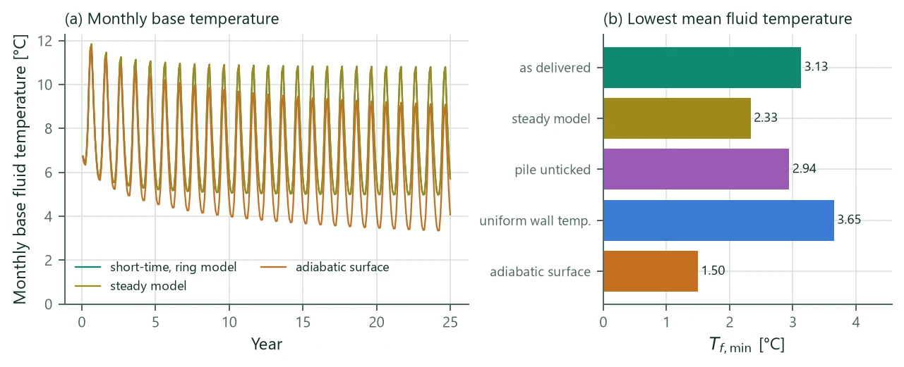
A small office on 24 bored piles of 20 m, diameter 600 mm, on a 4 m grid; a double U-tube 32 × 2.9 mm on the cage; concrete 1.8 W/(m K) and 2.2 MJ/(m³ K); ground 2.0 W/(m K), undisturbed temperature 9.3 °C. About 29 MWh/year heating (seasonal performance factor 3.8) and 12 MWh/year cooling as monthly loads, 25 years, limits 0 / 25 °C. The pile resistance is 0.0822 m K/W. Table 32 lists the project as delivered and four variants that each change one setting.
| Run | [°C] | [°C] | min / max [K] | Restrained [MPa] |
|---|---|---|---|---|
| As delivered: short-time model (ring model), uniform heat flux, isothermal surface | 3.13 | 3.00 | −3.98 / +2.12 | −1.19 / +0.63 |
| Steady resistance model | 2.33 | 2.20 | −3.97 / +2.12 | −1.19 / +0.64 |
| Energy pile unticked (short-time model with the equivalent pipe) | 2.94 | 2.81 | – | – |
| Uniform wall temperature | 3.65 | 3.52 | −3.43 / +2.21 | −1.03 / +0.66 |
| Adiabatic ground surface | 1.50 | 1.36 | −5.62 / +2.00 | −1.69 / +0.60 |
The concrete storage of the ring model raises by 0.80 K against the steady model; the equivalent pipe recovers only 0.61 K of it. The uniform wall temperature gives 0.52 K more, which is not conservative; an insulated slab (adiabatic surface) lowers by 1.63 K (Figure 19). The screening hardly depends on the borehole model, because it uses the monthly base; it does depend on the ground surface: −5.62 K instead of −3.98 K with the adiabatic surface. For the delivered project the free length change of a 20 m pile is −0.80 mm in heating to +0.42 mm in cooling (strain −40 / +21 µε), and fully restrained −1.19 MPa (tension) to +0.63 MPa (compression). The largest cooling of the pile comes in year 25, because the ground around a heating-dominated field keeps cooling for years; the largest heating comes in year 1, before that drift. The coldest fluid (3.13 °C mean, 3.00 °C at the inlet) is a short peak; the pile as a whole sees the monthly base.
20.6 Verification
- Numerics. The finite volumes of the ring model agree with the exact Laplace-domain solution of the same idealisation (inverted after Stehfest 1970) within 0.25 % from 10 min to 30 days.
- Ring idealisation against a 2D cross-section with individual pipes (2D finite volumes, 2.5 mm cells in the pile): the capacity effect agrees within 3–10 % of its largest value for piles of 0.3 to 1.2 m, where the equivalent pipe deviates by 10–18 %. Varying the position of the ring concrete shows the geometric rule (20.3) to be the only setting that is never worse than the equivalent pipe and stays at or below 10 % for all piles.
- Pile resistance. The concrete part of the multipole resistance agrees with the 2D cross-section within −1.6 to +4.2 %.
- Adiabatic surface. The mean of the adiabatic and isothermal responses equals the full-space finite line source (20.6) to .
20.7 Limits
- One mean pile: comes from the field's mean fluid temperature and is uniform along the pile. Centre piles of a group get colder than edge piles.
- In monthly mode the short peaks are not in ; hourly loads give it hour by hour.
- The ground surface is isothermal or adiabatic over the whole field.
- The screening is not a pile design: no load transfer, mobilised shaft friction or group effects.
- Loops in series do not work with borehole sections. Borehole sections enter the ring model with their length-weighted radius and concrete capacity, but the design's concrete conductivity.