 BoreTherm
Full FEM: Groundwater flow
Full FEM with the fully coupled TH ground: hydraulic boundary and initial conditions (prescribed head, flux, no flow; the regional head gradient and its direction), groundwater wells, the Darcy velocity to head gradient conversion and the background flow computation with its plan map.
What this page sets
This page appears under Input › Full FEM when Physics & run has the ground Fully coupled thermo-hydraulic (TH). The hydraulic properties of the layers and the water laws are on the Materials page.
- Boundary and initial conditions: top, bottom and sides with No flow, Prescribed head or Prescribed flux. A regional flow is given as the Head gradient on the faces with a prescribed head and its Flow direction (counter-clockwise from east). Initial state: hydrostatic (at rest) or the steady flow of the boundary conditions and wells.
- From the Darcy velocity… converts a Darcy velocity of the Ground page into the head gradient (v = K·i, K of the Materials page).
- Groundwater wells: position, screen, rate (> 0 injection) and the temperature of injected water.
- Compute groundwater flow computes the background flow alone (seconds) and shows the head or the Darcy velocity in a plan map at the chosen depth, with the mean and largest velocity and the water balance: check it before the 3D simulation. Show in the 3D view opens it on the 3D analysis page.
Values marked assumed (porosity, specific storage, water properties) are pre-filled; the coupled simulation never runs on them silently: the results page and the report list them.
Guided example: 13 Full FEM with groundwater flow (TH): a head gradient of 0.00044 gives 3.1 m/a in an aquifer of K ≈ 2.3·10⁻⁴ m/s.
Step-by-step workflows · Menus and keyboard
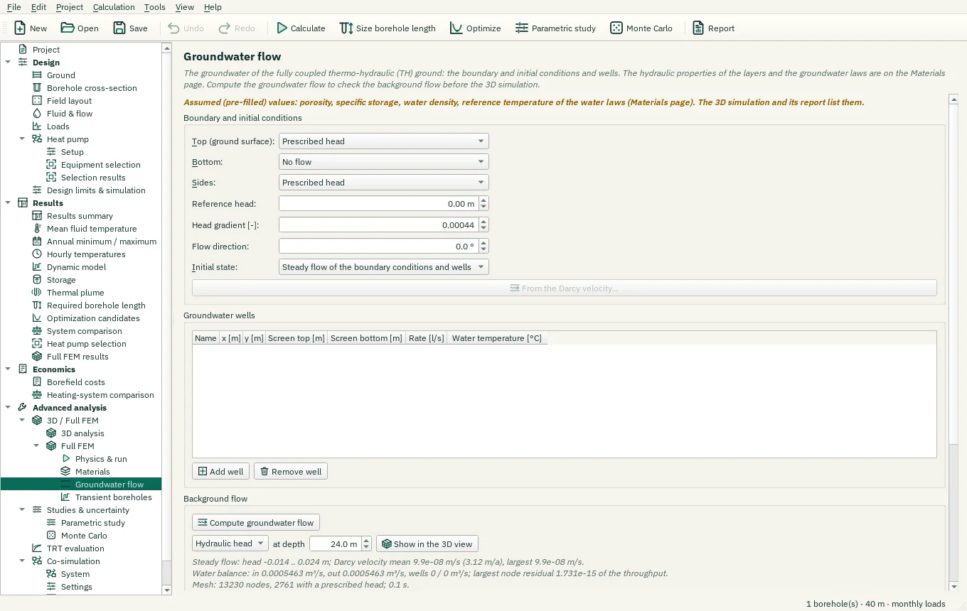
| Control | Meaning / action | Unit | Range / choices | Example value |
|---|---|---|---|---|
| Top (ground surface): | Select one of the listed alternatives. | No flow / Prescribed head / Prescribed flux | ||
| Bottom: | Select one of the listed alternatives. | No flow / Prescribed head / Prescribed flux | ||
| Sides: | Select one of the listed alternatives. | No flow / Prescribed head / Prescribed flux | ||
| Reference head: | Hydraulic head at the field centre on the ground surface, in metres above the ground surface (0: the water table at the surface). | m | -10000 to 10000 | 0 |
| Head gradient [-]: | Regional hydraulic gradient |grad h| on the faces with a prescribed head (e.g. 0.002). | 0 to 1 | 0.00044 | |
| Flow direction: | Direction of the regional flow (falling head), counter-clockwise from +x (east). | ° | -360 to 360 | 0 |
| Top flux: | Recharge through the ground surface (> 0 into the ground). | mm/a | -1e+06 to 1e+06 | 0 |
| Bottom flux: | Darcy flux through the bottom (> 0 into the ground). | mm/a | -1e+06 to 1e+06 | 0 |
| Side flux: | Darcy flux through the sides (> 0 into the ground). | mm/a | -1e+06 to 1e+06 | 0 |
| Initial state: | Select one of the listed alternatives. | Hydrostatic (at rest) / Steady flow of the boundary conditions and wells | ||
| From the Darcy velocity… | Converts the Darcy velocity entered on the Ground page into the head gradient that carries it (v = K i) and sets the prescribed velocity to 0 (the fully coupled ground computes the flow). | |||
| Add well | Runs the named action. | |||
| Remove well | Runs the named action. | |||
| Compute groundwater flow | The initial groundwater state of the 3D simulation (hydrostatic or the steady flow) on the 3D analysis mesh, with its water balance. | |||
| Gw map field | Select one of the listed alternatives. | Hydraulic head / Darcy velocity | ||
| Gw map depth | Depth of the plan map. | m | 0 to 10000 | 24 |
| Show in the 3D view | Runs the named action. | |||
| Cancel | Close without accepting unapplied edits. | |||
| Reference head: | Hydraulic head at the field centre on the ground surface, in metres above the ground surface (0: the water table at the surface). | ft | -32808.4 to 32808.4 | 0 |
| Gw map depth | Depth of the plan map. | ft | 0 to 32808.4 | 0 |