 BoreTherm
Full FEM: Physics & run
Full FEM chooses the physics of the direct 3D simulation: a simple or a fully coupled thermo-hydraulic (TH) ground, steady-state or full transient boreholes, the loop control, the time stepping and its step tolerance, the initial state, the thermal boundaries and the coupling; it runs the full 3D simulation and sizes the length with the 3D model (Size with 3D). The default step tolerance 0.01 K suits monthly design runs; set 0.003 K for hourly or short-time results and after a load or pump stop with transient boreholes.
What this page sets
This page appears under Input › Full FEM when the Project page has 3D analysis: Full FEM. The mesh, the domain and the solver of the 3D model stay on the 3D analysis page; Calculate (F5), sizing, optimisation and the studies stay 2D.
- Physics › Ground: Simple (heat conduction, optionally with a prescribed groundwater velocity from the Ground page) or Fully coupled thermo-hydraulic (TH) (groundwater pressure, flow and heat transport solved together; buoyancy and temperature-dependent viscosity; the Groundwater flow page appears). Boreholes: Steady-state (borehole resistances at every step) or Full transient (fluid transit and heat stored in the fluid, the pipe walls and the grout; the Transient boreholes page appears). Every combination runs; the line below the selectors names the calculation.
- Darcy velocity to head gradient… (fully coupled TH): converts a Darcy velocity entered on the Ground page into the regional head gradient of the Groundwater flow page (v = K·i) in one undo step. The coupled ground does not run with a prescribed velocity.
- Loop control: Automatic (default) prescribes the heat rate of the fluid loop for transient boreholes (the heat pump's rate; the borehole storage delays the load on the ground) and the ground load at the borehole wall for steady-state boreholes. Inlet temperature (time series) needs time-series loads with an inlet-temperature column.
- Time stepping: Adaptive (step ladder) chooses each step from the error estimate; the steps are the smallest step times powers of 2, so solver factorisations are reused. Initial step is the first step after every change of the load, Largest step caps the step. Fixed step is for verification.
- Peak loads as trial branches (monthly loads): each month's peak (classic monthly method) is computed as a side branch from the base state, as in the 2D design; it does not enter the operational history.
- Initial state: the geothermal profile (surface temperature and heat flux, layered) or the project mean temperature (for a one-to-one comparison with the 2D design). Thermal boundaries: top, bottom and sides at the initial temperature, without heat flux, or (bottom) with the geothermal heat flux; the temperature of groundwater entering the block.
- Coupling (fully coupled TH): iterations per step, relaxation and the temperature and pressure tolerances of the iteration between flow and heat transport. The defaults are converged (benchmark B8: 10⁻⁶ K changes the results by 5·10⁻⁸ K).
- Run full 3D simulation starts the run; the line below estimates unknowns, steps, time and memory. Size with 3D… sizes the borehole length with the selected 3D model (every trial length is a full run, starting from the 2D size) and offers to apply it in one undo step.
Step tolerance for short-time results
The default tolerance of 0.01 K per step is right for monthly design runs (benchmark B8: halving it changes the monthly results by 0.011 K). For hourly or other short-time results, and for the first output interval after a load stop or a pump stop with transient boreholes, set a tighter tolerance, for example 0.003 K, in Time stepping › Tolerance on this page, and run again. With the default, the benchmark campaign found 0.10–0.16 K in hourly cases and up to 1.1 K in the first 10 minutes after a load stop (B3); with 0.003 K these cases are within 0.05–0.07 K, at 1.3–1.6 times the run time. In tutorial 12 the lowest fluid temperature in the first hour after the load stop is 2.58 °C with 0.01 K and 1.23 °C with 0.003 K, while the hourly means differ by at most 0.05 K.
Guided examples: 12 Full FEM with transient boreholes · 13 Full FEM with groundwater flow (TH). Validation: Methods and verification.
Step-by-step workflows · Menus and keyboard
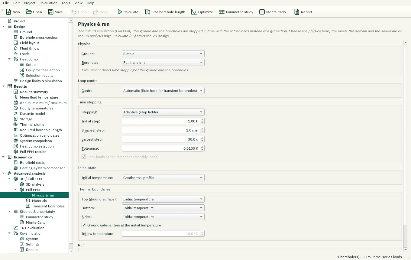
| Control | Meaning / action | Unit | Range / choices | Example value |
|---|---|---|---|---|
| Ground: | Simple: heat conduction in the ground with the groundwater flow entered on the Ground page. Fully coupled TH: the groundwater pressure and flow are calculated together with the temperature (buoyancy, temperature-dependent viscosity). | Simple / Fully coupled thermo-hydraulic (TH) | ||
| Boreholes: | Steady-state: the inside of the borehole is in equilibrium at every step (borehole resistances). Full transient: fluid, pipes and grout store heat and the fluid needs time to travel through the borehole. | Steady-state / Full transient | ||
| Darcy velocity to head gradient… | The fully coupled ground calculates the groundwater flow from heads. Converts the Darcy velocity entered on the Ground page into the regional head gradient that carries the same flow (v = K i). | |||
| Control: | What the loads prescribe: the heat rate through the borehole walls (the meaning of every load input), the heat rate of the fluid loop (equal with steady-state boreholes), or the inlet temperature of a time series (Tin column); exactly one closes the loop. Automatic: the fluid loop with transient boreholes (the heat pump's heat rate; the borehole storage delays the ground load), the borehole wall with steady-state boreholes. | Automatic (fluid loop for transient boreholes) / Ground load at the borehole wall / Heat rate of the fluid loop / Inlet temperature (time series) | ||
| Stepping: | Adaptive: backward Euler with an error estimate by step doubling; the steps are the smallest step times a power of 2, so every factorisation is reused. Fixed: the initial step throughout (verification). | Adaptive (step ladder) / Fixed step | ||
| Initial step: | First step after every change of the load (Fixed: every step). | h | 0.01 to 720 | 1 |
| Smallest step: | Smallest step: the base of the step ladder (smallest step × 2^k). | min | 1 to 1440 | 1 |
| Largest step: | Largest step. | d | 0.1 to 365 | 30 |
| Tolerance: | Local error per step of the temperatures (adaptive stepping). | K | 0.0001 to 1 | 0.01 |
| Peak loads as trial branches (monthly loads) | Monthly peaks of the classic method: each peak replaces the base load for its duration at the end of the month, computed from the base state without changing the operational history. | |||
| Initial temperature: | Geothermal profile: surface temperature and geothermal heat flux through the layers. Project mean temperature: the undisturbed temperature of the design everywhere, for a one-to-one comparison with the g-function calculation. | Geothermal profile / Project mean temperature | ||
| Top (ground surface): | Initial temperature: the face keeps the initial temperature (as the g-function calculation). No heat flux: no conduction through the face; groundwater still carries heat in and out. Geothermal heat flux (bottom): the geothermal heat flux of the Ground page enters the block. | Initial temperature / No heat flux | ||
| Bottom: | Initial temperature: the face keeps the initial temperature (as the g-function calculation). No heat flux: no conduction through the face; groundwater still carries heat in and out. Geothermal heat flux (bottom): the geothermal heat flux of the Ground page enters the block. | Initial temperature / No heat flux / Geothermal heat flux | ||
| Sides: | Initial temperature: the face keeps the initial temperature (as the g-function calculation). No heat flux: no conduction through the face; groundwater still carries heat in and out. Geothermal heat flux (bottom): the geothermal heat flux of the Ground page enters the block. | Initial temperature / No heat flux | ||
| Groundwater enters at the initial temperature | Water flowing into the block through a face with no heat flux or the geothermal heat flux has the initial temperature there; otherwise the temperature below. | |||
| Inflow temperature: | Temperature of the groundwater entering the block. | °C | -20 to 100 | 10 |
| Iterations per step: | Largest number of coupling iterations of groundwater flow and heat transport per time step; a step that does not converge is repeated with half the step. | 1 to 1000 | 25 | |
| Relaxation: | Under-relaxation of the head update between the iterations (1: none). Lower it when the coupling oscillates. | 0.05 to 1 | 1 | |
| Temperature tolerance: | Converged when the temperatures change by less than this between two iterations (plus the relative tolerance). | K | 1e-06 to 1 | 0.0001 |
| Pressure tolerance: | Converged when the pressures change by less than this between two iterations (plus the relative tolerance). | Pa | 0.001 to 100000 | 1 |
| Run full 3D simulation | Steps the current design in time with the actual loads (Shift+F5); saved or cached results of the same inputs are reused. The results are under Results › Full FEM results. | |||
| Size with 3D… | Finds the borehole length for which this full 3D model keeps the fluid temperatures within the design limits: every trial length is a full 3D simulation from the undisturbed ground (several runs; it starts at the 2D size). Calculate (F5), the optimisation and the studies stay 2D. | |||
| Tolerance: | Local error per step of the temperatures (adaptive stepping). | °F | 0.0002 to 1.8 | 0.018 |
| Inflow temperature: | Temperature of the groundwater entering the block. | °F | -4 to 212 | 50 |
| Temperature tolerance: | Converged when the temperatures change by less than this between two iterations (plus the relative tolerance). | °F | 2e-06 to 1.8 | 0.00018 |