 BoreTherm
Full FEM: Transient boreholes
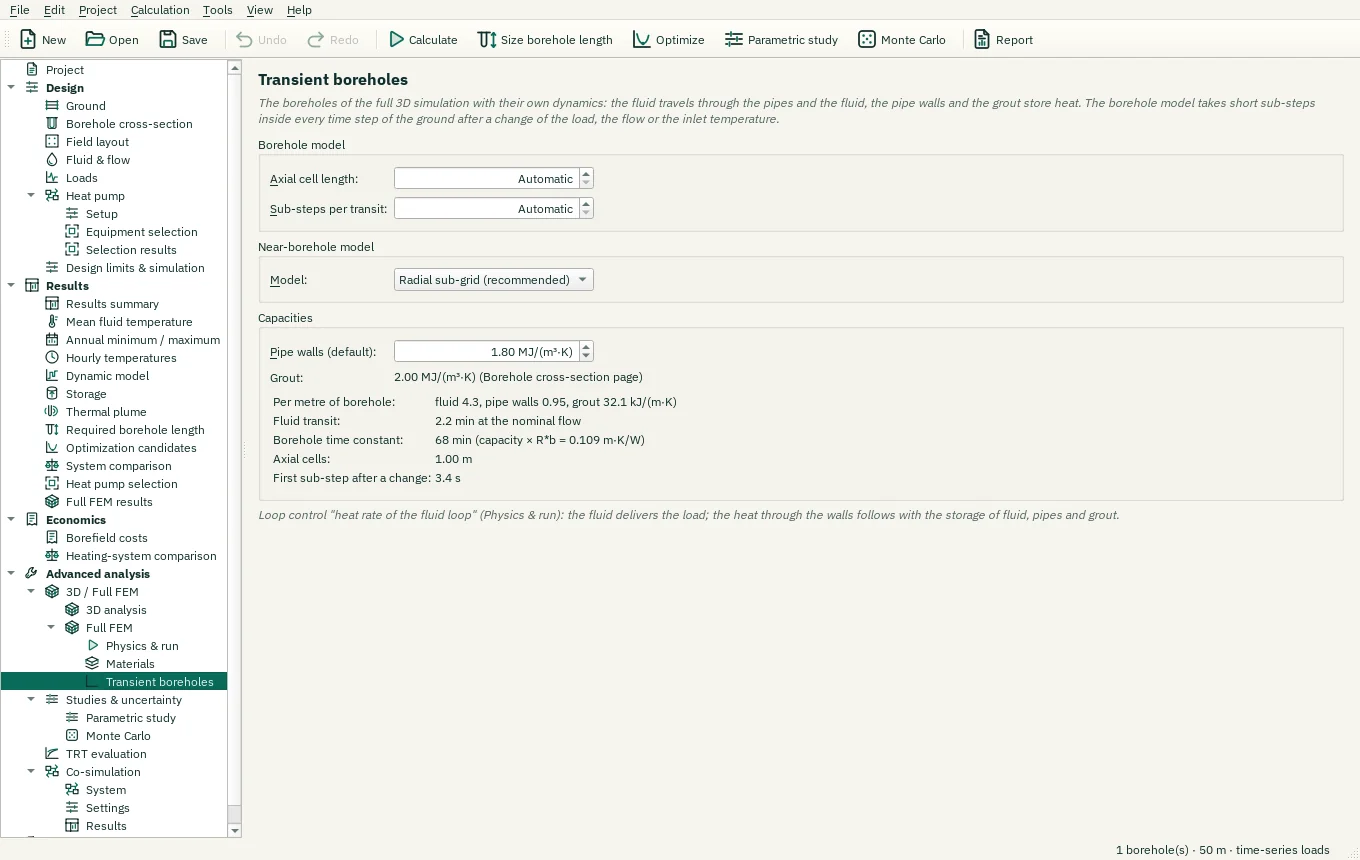
Full FEM with full transient boreholes: the axial cell length and sub-steps of the borehole columns, the near-borehole model (radial sub-grid or well index) and the heat capacities of the pipe walls and the grout, with the capacities per metre, the fluid transit time and the borehole time constant.
What this page sets
This page appears under Input › Full FEM when Physics & run has the boreholes Full transient. The boreholes then have their own dynamics: the fluid travels through the pipes (transit time), and the fluid, the pipe walls and the grout store heat. Inside every time step of the ground the borehole model takes short sub-steps after each change of the load, the flow or the inlet temperature.
- Axial cell length (Automatic = 1 m) and Sub-steps per transit (Automatic = 40): the resolution of the borehole columns. The defaults are converged (benchmark B3: 0.5 m and 80 sub-steps change the fluid temperature by ≤ 0.003 K).
- Near-borehole model: Radial sub-grid (recommended) resolves the grout and the near ground radially at every axial cell and is insensitive to the mesh around the borehole; Well index of the mesh is the steady coupling of the Simple FEM (slow for short times: up to 2–3 K in the first hours, benchmark B3).
- Capacities: the default heat capacity of the pipe walls (PE about 1.8 MJ/(m³·K); per pipe and per section on the Borehole cross-section page, e.g. a steel casing), the grout capacity from the Borehole cross-section page, and the resulting capacities per metre, the fluid transit time, the borehole time constant (capacity × R*b), the axial cells and the first sub-step.
The borehole time constant tells where transient boreholes matter: for load changes shorter than a few time constants (typically 0.5–2 h) the fluid temperature differs from the steady borehole model; for monthly design loads the difference is small.
Step tolerance: the default 0.01 K is right for monthly design runs. For hourly or short-time results, and for the first output interval after a load stop or a pump stop, set a tighter tolerance such as 0.003 K on Physics & run (Time stepping › Tolerance).
Guided example: 12 Full FEM with transient boreholes.
Step-by-step workflows · Menus and keyboard
| Control | Meaning / action | Unit | Range / choices | Example value |
|---|---|---|---|---|
| Axial cell length: | Length of the axial cells of the borehole model (fluid, pipes, grout). The upwind transport of the fluid spreads a temperature front by about half a cell per cell passed; shorter cells keep the front sharper. Automatic: 1 m (at most 400 cells per borehole). | m | 0 to 50 | 0 |
| Sub-steps per transit: | Borehole sub-steps per fluid transit after a change of the input (multirate: the borehole is stepped inside every time step of the ground, so the transit is resolved without shortening the 3D step). Automatic: 40. | 0 to 1000 | 0 | |
| Model: | How the borehole wall sees the ground mesh at short times. Radial sub-grid: a fine radial model of the ground from the borehole wall to about two mesh cells, accurate for pulses of minutes to hours. Well index: the mesh node alone, accurate only after the validity time of the mesh (hours to days; for comparisons with other finite-element codes). Used by every direct 3D simulation. | Radial sub-grid (recommended) / Radial sub-grid / Well index of the mesh | ||
| Pipe walls (default): | Volumetric heat capacity of the pipe walls (PE / PE-X: about 1.8 MJ/(m³·K)) for the pipes without their own value on the Borehole cross-section page (a steel casing there: about 3.6). It is counted once, at the grout node next to each pipe (coaxial: the inner pipe at its own wall node). 0: pipe walls without capacity, as in the thermal resistance and capacity model (TRCM) of Bauer et al. and in the dynamic borehole model. | MJ/(m³·K) | 0 to 10 | 1.8 |
| Axial cell length: | Length of the axial cells of the borehole model (fluid, pipes, grout). The upwind transport of the fluid spreads a temperature front by about half a cell per cell passed; shorter cells keep the front sharper. Automatic: 1 m (at most 400 cells per borehole). | ft | 0 to 164.04 | 0 |